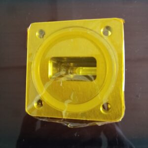
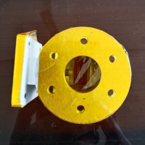
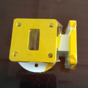
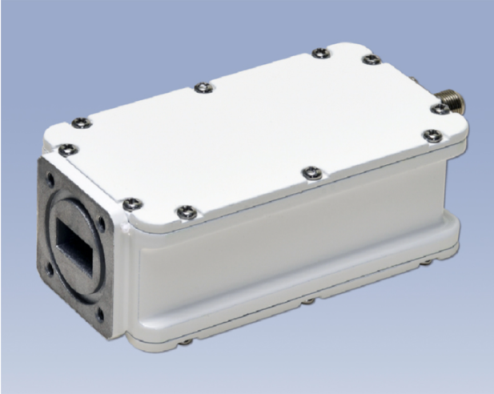
• Working frequency band: 10700 – 14500 GHz
• Both ports are Rx only.
• Insertion loss: < 0.2 dB Polarization isolation: > 25 dB
• VSWR: 1.20:1 Max
• Interface: WR75
The Ku-Band OMT offers a range of benefits that make it an indispensable component in modern satellite communication systems. Below are the primary features and advantages:
• Dual-Polarization Capability: The OMT is designed to handle both horizontal and vertical polarization, which effectively doubles the available communication capacity without the need for additional bandwidth.
• Low Insertion Loss: The OMT is engineered to minimize signal loss, ensuring that the transmitted and received signals maintain high integrity and clarity.
• High Isolation: One of the key features of the Ku Band OMT is its ability to provide excellent isolation between the polarization channels, preventing signal interference and ensuring reliable communication.
• Compact and Durable Design: The OMT is compact and lightweight yet highly durable, making it suitable for both terrestrial and space-based satellite communication systems.
• Wideband Operation: The OMT operates across the entire Ku Band range (12 GHz to 18 GHz), ensuring compatibility with a wide variety of communication applications.
• Reliability: Built to withstand harsh conditions, the Ku Band OMT is designed for long-term operation, even in challenging environmental conditions.
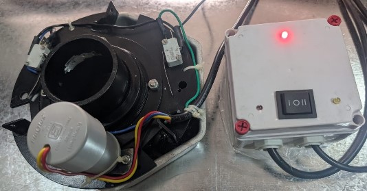
•On both ports use 2 Lnbs for receiving
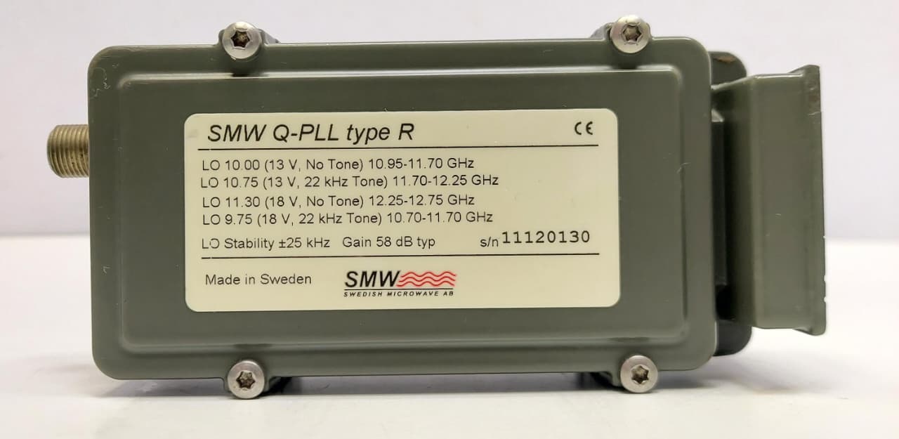
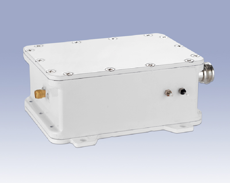
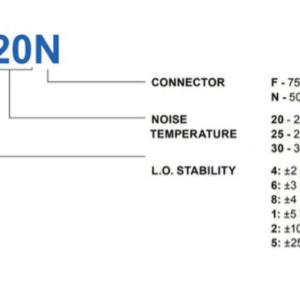
Used SMW Q-PLL KU-band LNB type R Full Band
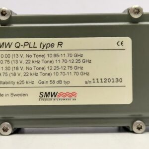
Frequency range: 10.700 – 12.750 GHz Complete Full KU band
Standard LO frequency: (max. 4) 10.000, 10.750 11.300, 9.750, GHz
Standard IF Frequency: 950-1450 to 2150 MHz
LO Stability: ±25
Gai: 58dB typ
Download
Datasheet
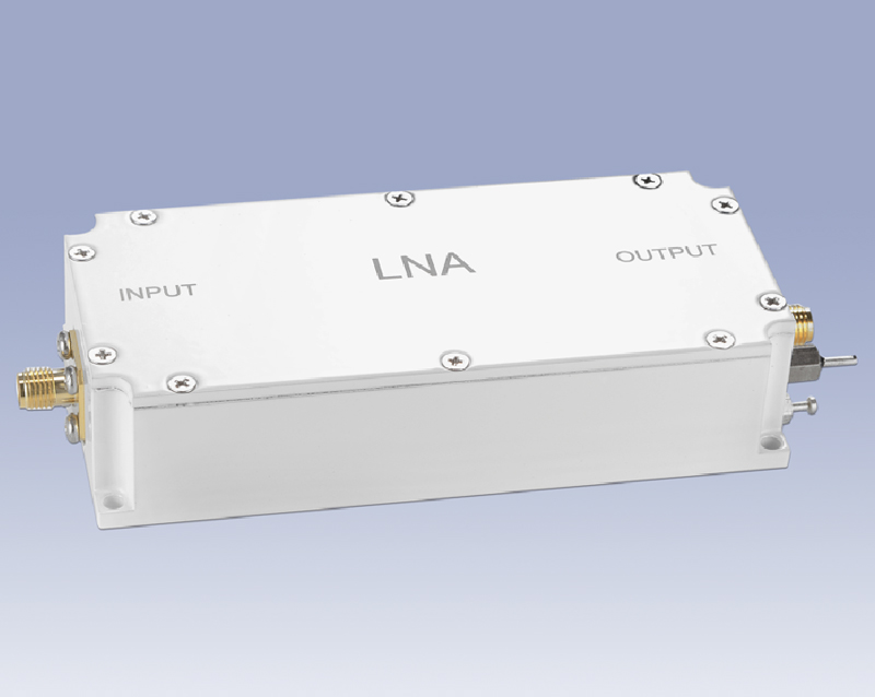
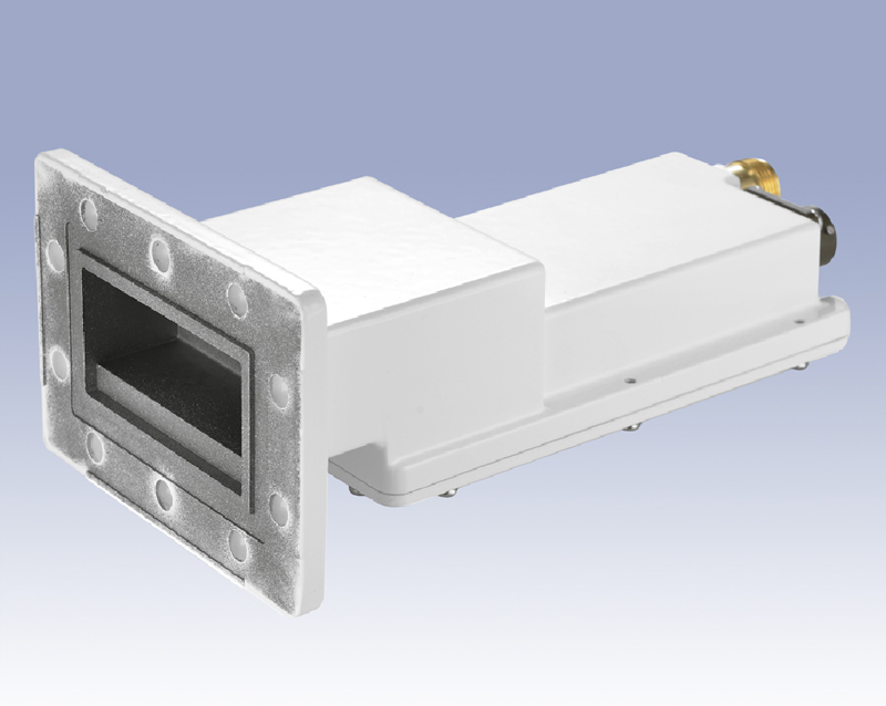
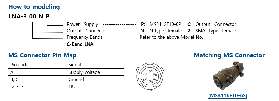
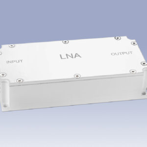
C-Band LNA (Low Noise Amplifier)
LNA-300 series
Model No. & Frequency (Customized frequency available)
| Model No |
Frequency Range |
Model No. |
Frequency Range |
| LNA-300 |
3.4 – 4.2 GHz |
LNA-320 |
3.625 – 4.2 GHz |
| LNA-310 |
4.5 – 4.8 GHz |
LNA-330 |
3.4 – 4.2 GHz |
Technical Specifications
| Parameter |
Specification |
Parameter |
Specification |
| Noise temperature |
30’K max. (LNA-310 : 40’K max.) |
Output connector |
N, SMA type female |
| Gain |
60 dB typ |
Power supply |
+12 to +24V DC |
|
(55 dB min, 65 dB max.) |
Power supply connector |
MS3112E10-6P |
| Gain flatness |
4 dBp-p max. |
Matching MS connector |
MS3116F10-6S |
| Gain ripple at per 36 MHz |
1 dBp-p max |
Required current |
200 mA max. |
| Output P1dB |
+5 dBm min. |
Operating temperature |
-40 to +60℃ |
| Input VSWR |
2.2: 1-max. |
Waterproof |
IP 67 |
| Output VSWR |
2.2: 1-max. |
Dimension |
98.8 x 70.0 x 164.5 mm |
| Input W/G flange |
CPR 229G (with groove) |
Weight |
630 g |
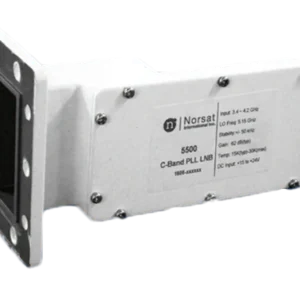
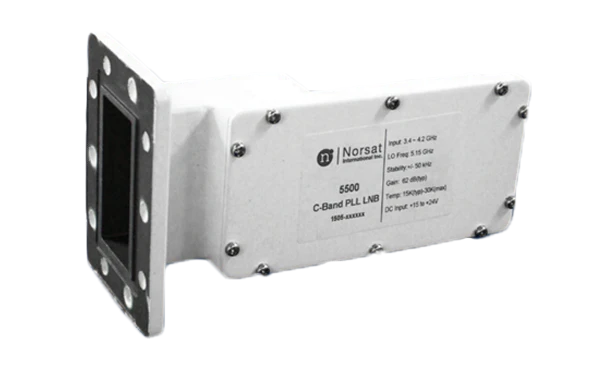
NORSAT 5000 C-BAND PLL LNB +/-50 KHZ
Ideal for DVB (Digital Video Broadcast), VSAT Broadband, Military Satcom, Point-of-Sale, and Oil and Gas applications
- Input Frequency: 3.4 – 4.2 GHz
- L.O. Stability: +/-50 kHz
- Noise Figure: 15K typical
- Output Connector: F-Type Female
- L.O. Frequency: 5.15 GHz
- Conversion Gain: 62 dB typical
- Output frequency (MHz): 950 – 1750 MHz
5000-Spec-Sheet
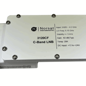
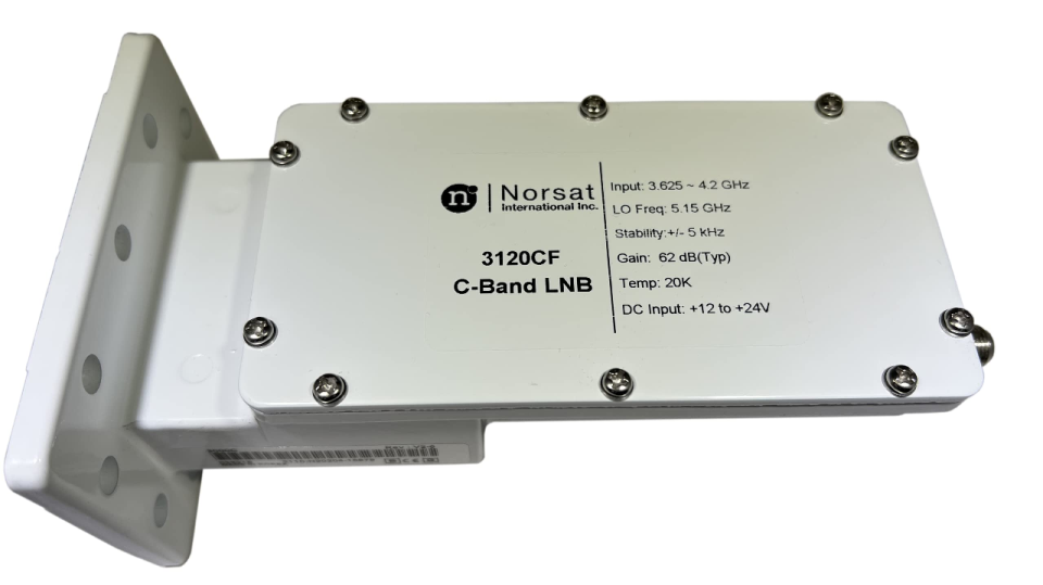
Norsat 3220 Series High Stability C-Band PLL LNB
Norsat’s Low Noise Blocks (LNBs) provide signal reception for satellite communications around the world. We offer premium performance and reliability in the smallest form factor possible. All of their standard C-Band LNBs are backed by a 3-year warranty and nearly forty years of experience as the industry’s leading provider of high performance LNBs.
- Input Frequency: 3.4 – 4.2 GHz
- L.O. Stability:
- Noise Temperature: 20 K
- Output Connector: F-Type Female
- L.O. Frequency: 5.15 GHz
- Conversion Gain: 62 dB
The Norsat 3220 C-Band PLL LNB is one of Norsat’s many premium quality C-Band LNBs. It is a preferred LNB for many C-band applications.
Applications
- Low data rate digital video
- A reference LNB for Rx test and service
- SCPC digital or analog audio applications
- Low-speed SCPC data from 19.2 – 512 Kbps, or any higher data rate
Norsat Advantages
- 3-Year Warranty
- Norsat LNBs are graded by stability and Noise Temperature to provide the perfect balance between required performance and cost.
- Proven reliability for lower lifetime costs.
- Excellent PLL LO stability to control receiver drift and employ lower bit rates or narrower space segments
- Excellent Phase Noise to Lower Carrier to Noise margins, improving BER
Frequency Band Available
| INTERFACE SPECIFICATIONS |
| RF Input Connector |
CPR 229G waveguide grooved |
| RF Output Connector |
F-75 Ohm |
| M & C SPECIFICATIONS |
| LED Indicators |
None |
| ENVIRONMENTAL SPECIFICATIONS |
| Temperature – Operational |
-40 to +60°C |
| Temperature – Storage |
-40 to +80°C |
| Product Family |
3000 Series |
| Band |
C-Band |
| LO Type |
PLL |
| # of onboard LOs |
Single-band |
| LO Stability |
+/- 5 kHz |
| Noise Figure |
20 K |
| Input Frequency – Band |
C-Band: 3.625 – 4.20 GHz |
| Output Frequency |
L-Band: 950 – 1525 MHz |
Specification Sheet
3000C-Spec-Sheet
S-Band BDC (Block Down Converter)
| BDC-S series |
Internal reference |
| BDC-SX series |
External reference |
Model No. & Frequency (customized frequency available)
| Model No. |
Input Freq. (MHz) |
Output Freq. (MHz) |
L.O Freq. (GHz) |
| BDC-S-2200-2290 |
2200 – 2290 |
950 – 1040 |
3.24 |
| BDC-S-2200-2290X |
2200 – 2290 |
950 – 1040 |
3.24 |
Technical Specifications
| Parameter |
Specification |
Parameter |
Specification |
| Noise figure |
10 dB max. |
Ext. input freq. & power |
10 MHz, -5 to +5 dBm |
| Conversion gain |
30 dB typ. |
Ext. input port |
IF output connector |
|
(27 dB min. 33 dB max.) |
Input VSWR |
2.0: 1 max. |
| Gain flatness |
2 dBp-p max. |
Output VSWR |
2.0: 1 max. |
| Gain ripple at per 36MHz |
0.5 dBp-p max. |
Input connector |
SMA type female |
| L.O stability |
Internal: ±5, 10, 25 KHz max. |
Output connector |
F or N, SMA type female |
|
External : depends on ext. ref. |
Power supply |
+12 to +24V DC |
| Image rejection |
40 dBc min. |
Power supply connector |
Feed and/or output con. |
| Phase noise |
-85 dBc/Hz at 1KHz |
Required current |
300 mA max. |
|
-90 dBc/Hz at 10KHz |
Operating temperature |
-40 to +60℃ |
|
-95 dBc/Hz at 100KHz |
Waterproof |
IP 67 |
|
+5 dBm min. |
Dimension |
108.0 x 94.0 x 46.0 mm |
|
+15 dBm min. |
Weight |
620 g |
| BDC-S–2200-2290 X S D 25 |
|
|
LO Stability |
Blank: External, 05: ±5KHz, 10: ±10KHz, 25: ±25KHz |
|
Power Supply |
D: Feed & output connector, C: Output connector only |
|
|
P: Feed through connector only |
|
Output Connector |
F: F-type female, N: N-type female, S: SMA type female |
|
10-MHz Reference |
Blank: Internal, X: External reference |
|
Frequency Bands |
Refer to the above Model No. |
|
S-Band BDC |
BDC-S–2200-2290 X S D 25 |
L, S-Band LNA (Low Noise Amplifier)
| LNA-1000 series |
L-Band LNA |
| LNA-2000 series |
S-Band LNA |
Model No. & Frequency (Customized frequency available)
| Model No. |
Frequency Range |
|
|
| LNA-1100-1700 |
1100 – 1700 MHz |
|
|
| LNA-1150-1650 |
1150 – 1650 MHz |
|
|
| LNA-1400-1600 |
1400 – 1600 MHz |
|
|
| LNA-2100-2500 |
2100 – 2500 MHz |
|
|
Technical Specifications
| Parameter |
Specification |
Parameter |
Specification |
| Noise temperature |
40’K max. |
Power supply |
+12 to +24V DC |
| Gain |
60 dB typ.
(55 dB min. 65 dB max.)
|
Power connector options |
Output, Feed through connector, Separated SMA connector, MS3112E8-4P connector |
| Gain flatness |
2 dBp-p max. |
|
|
| Gain ripple at per 36MHz |
1 dBp-p max. |
Required current |
300 mA max. |
| Output P1dB |
+10 dBm min. |
Operating temperature |
-40 to +60℃ |
| Input VSWR |
2.0 : 1 max. |
Waterproof |
IP 67 |
| Output VSWR |
2.0 : 1 max. |
Dimension |
22.6(24.6) x 45.0 x 100.0 mm
|
| Input connector |
N, SMA type female |
Weight |
250 g |
| Output connector |
F, N, SMA type female |
|
|
| LNA–1100-1700 N N–FC |
|
|
Power Connector
|
FC: Feed through connector, OC: Output connector
2S: Separated SMA connector MS4: MS3112E8-4P |
|
Output Connector |
F: F-type female, N: N-type female, S: SMA type female |
|
Input Connector |
N: N-type female, S: SMA type female |
|
Frequency Bands |
Refer to the above Model No. |
|
LNA series |
LNA–1100-1700 N N–FC |
Specifications
| A500-137-142 |
Internal reference |
| A500-137-142X series |
External reference |
Model No. & Frequency (Customized frequency available)
| Model No. |
Input Freq. (GHz) |
Output Freq. (MHz) |
L.O Freq. (GHz) |
| A500-137-142X |
13.7 – 14.2 |
900–1400 |
12.8 |
Technical Specifications
| Parameter |
Specification |
Parameter |
Specification |
| Noise figure |
0.8 dB max. |
Ext. input freq. & power |
10 MHz, -5 to +5 dBm |
| Conversion gain |
60 dB typ. |
Ext. input port |
IF output connector |
|
(55 dB min. 65 dB max.) |
Input VSWR |
2.5: 1 max. |
| Gain flatness |
4 dBp-p max. |
Output VSWR |
2.5: 1 max. |
| Gain ripple at per 36MHz |
1 dBp-p max. |
Input waveguide flange |
WR 75 (with groove) |
| L.O stability |
Internal: ±5, 10, 25 KHz max. |
Output connector |
F or N-type female |
|
External: depends on ext. ref. |
Power supply |
+12 to +24V DC |
| Image rejection |
40 dBc min. |
Required current |
350 mA max. |
| Phase noise |
-70 dBc/Hz at 1KHz |
Operating temperature |
-40 to +60°C |
|
-80 dBc/Hz at 10KHz |
Waterproof |
IP67 |
|
-95 dBc/Hz at 100KHz |
Dimension |
60.0 x 41.6 x 111.5 mm |
| Output P1dB |
+5 dBm min. |
Weight |
380 g |
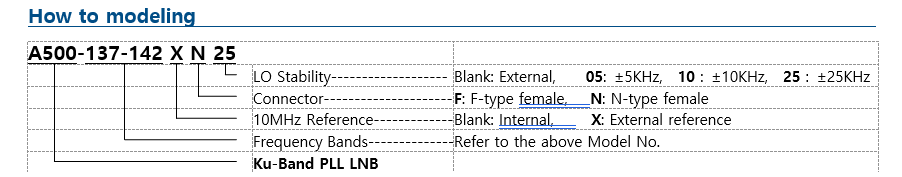
| A500–137-142 X N 25 |
|
|
LO Stability ——— |
Blank: External, 05: ±5KHz, 10: ±10KHz, 25: ±25KHz |
|
Connector ———– |
F: F-type female, N: N-type female |
|
10MHz Reference — |
Blank: Internal, X: External reference |
|
Frequency Bands — |
Refer to the above Model No. |
|
A500 |
Ku-Band PLL LNB |
3-Axis Motorized K/KU/C-band Dish antenna
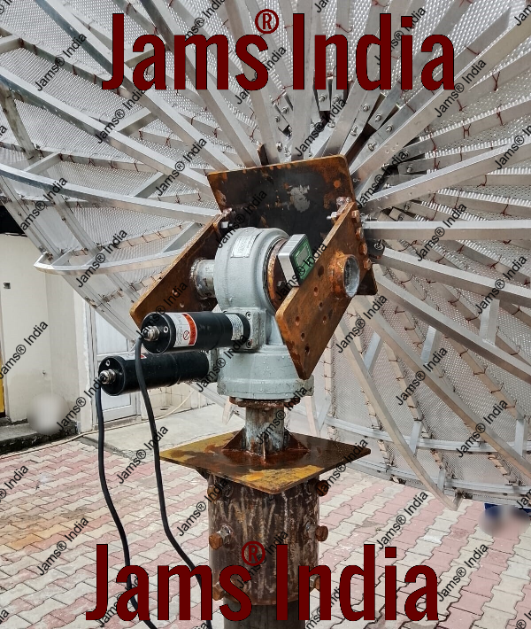
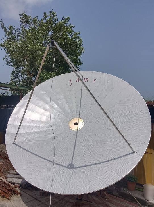
Size available 12-ft, 16-ft, 24-ft.
Motorized LNB feed polarizer covers horizontal, vertical, and circular (LHCP, RHCP) polarization.
We are offering customized motorized LNB polarizers for C band, Ku band, Ka band, and S band LNB.